Simulation via the Finite Element (FE) method requires the utilization of a simulation mesh. Nowadays, simulation meshes are being generated by simulation software automatically; integrated automatic meshing algorithms “split” three-dimensional (3D) designs into smaller (finite) elements that will essentially represent the geometry. In addition to the splitting, mesh algorithms commonly allow defining in what types of elements designs should be divided; commonly choices include tetrahedral and hexahedral elements.

The figure above shows schematically a 4-node tetrahedral element and an 8-node hexahedral element.
Both element types come with certain advantages and disadvantages that are predominantly related to mesh generation, simulation accuracy, and numerical stability. Tetrahedral elements, for example, are very suitable for representing very complex structures but are known to yield less accurate results with the same mesh resolution. While hexahedral elements can provide more accurate simulation results, they are often less suitable to geometrically discretize very complex geometries. More specifically, it is often not possible to utilize them, allowing a perfect representation of the geometrical boundaries of a design.
Particularly for Additive Manufacturing (AM) a common way to apply hexahedral elements is via voxel-mesh technique. This technique overlays a voxelized grid to approximate the underlying geometry, however, with this technique, geometrical misrepresentation of the geometry is likely to occur. In order to properly use voxel-meshes for simulation, elemental stiffness correction needs to be performed by lowering and increasing the elemental stiffness for regions that are under- and over-represented with the hexahedral elements, respectively.
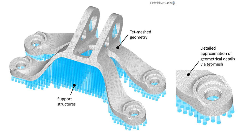
The figure above shows an engine bracket simulation model meshed with tetrahedral elements. The original geometry can be nicely approximated via the tetrahedral mesh.

The figure above shows an engine bracket simulation model meshed with hexahedral elements. The original geometry is approximated via the hexahedral mesh.
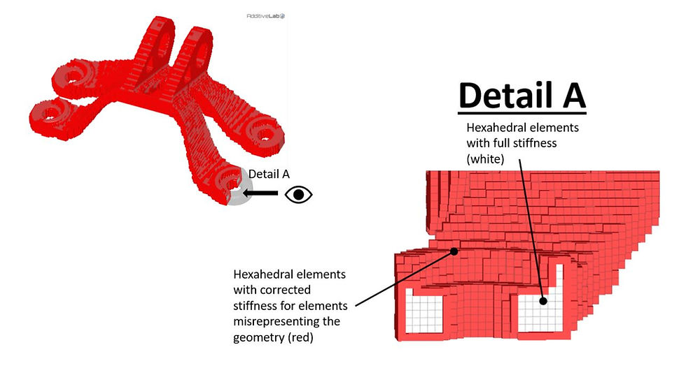
The figure above shows the hexahedral elements with corrected stiffness for elements misrepresenting the geometry (red) and the ones within the geometry with full stiffness.
Do you need more info or a demo? Write us an email via info@additive-lab.com
Comments